Peavey PCX-U302 User Manual
Browse online or download User Manual for Supplementary music equipment Peavey PCX-U302. Peavey PCX-U302 User's Manual
- Page / 28
- Table of contents
- BOOKMARKS
Summary of Contents
PCX-U302PCX-U302PLL True diversityUHF wirelessreceiverPLL True diversityUHF wirelessreceiverOPERATING GUIDE
4. OPERATION INSTRUCTIONS1. Turn the volume controls of the receiver and device in use to a minimum setting before turning on the microphone transmit
illuminate according to the strength of sound level. If the LEDs do not illuminate or sound isnot present at the output, the system is not functioning
d. If the receiver output level is adjusted to a level that is near the maximum input level of the desired device, it will cause saturation distortio
13SELECTING A FREQUENCY CHANNEL ON THE RECEIVERYour local dealer/distributor should be able to adviseyou on the best frequency selection for your area
HANDHELD WIRELESS MICROPHONE TRANSMITTERLike the receiver, the hand held microphone featuresadvanced synthesized PLL design. It is preprogrammedwith 3
on indicates that the battery is either dead or not installed. A constant glow indicates a weakbatter that should be replaced.5. On-Of switch. Push f
162. BATTERY INSTALLATIONFig.121. Unscrew the grill/ball screen assembly at the collar to expose the battery compartment.2. Insert the 9-volt batter
once audio is present. As mentioned previously, the level ofthese two indicators will indicate their signal strength at thereceiver. When the microph
18connection is used. If you are having problemswith a system, this is one of the first places to look for the solution.2. Transmit antenna: 1/4 wave
signal is present at the input (from a lapel microphone, guitar etc)8. Unused status indicator: this illuminates when the combination of group and ch
Intended to alert the user to the presence of uninsulated “dangerous voltage” withinthe product’s enclosure that may be of sufficient magnitude to con
203. Select a group/channel combination, making sure that it matches the combination already set on the receiver.4. Connect your lapel microphone, g
1. AF 4-PIN INPUT CONNECTION METHODS1. 2-Wire Electret condenser microphone Capsule2. 3-Wire Electret condenser microphone Capsule3. Dynamic Micropho
22SPECIFICATIONS1. Overall: UHF PCX-U3021. Carrier Frequency Range: UHF Band 790~960 MHz2. Oscillation Mode: PLL synthesized3. Frequency: Pre-progr
23TROUBLESHOOTING GUIDESymptom Distance Possible PossibleCause SolutionNo AF signal Any low transmitter replace batteryand no RF signal battery volt
NOTES:24
NOTES:25
PEAVEY ELECTRONICS CORPORATION LIMITED WARRANTYEffective Date: July 1, 1998What This Warranty CoversYour Peavey Warranty covers defects in material an
IMPORTANT SAFETY INSTRUCTIONSWARNING: When using electric products, basic cautions should always be followed, including the following:1. Read these i
Features and specifications subject to change without notice.Peavey Electronics Corporations • 711 A Street • Meridian MS • 39301 • (601) 483-5365 • F
INTRODUCTIONThank you for selecting a Peavey Pro Comm PCX-U302 quartz controlled single channel true diversity wirelessmicrophone system. Before opera
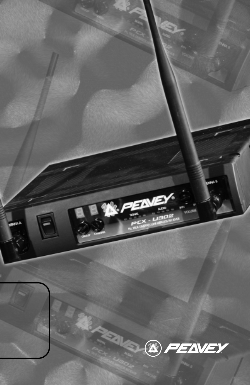
1. Antenna Input Connector A2. Power Switch and Indicator:When the switch is turned on the red indicator illuminates to denote normal power status.3.
10. Antenna Input Connector B REAR PANELB. Rear Panel11. DC 12V Input Jack: Connect the 12V DC plug from the AC/DC adapter.12. Balanced Audio Output
2. AC/DC Power Connection:Fig. 3Connect the AC/DC adapter cable to the DC 12V input jack. Then plug the adapter unit into an appropriate AC outlet as
desired device. Make sure the unbalanced level switch is in the proper position before applying power.c. Balanced Output:Connect the male XLR connecto
3. TWO 19/2-INCH UNITS RECEIVER INSTALLATIONA. Setup for single half-rack receiver1. Push the rack mount brackets (RM-11) upwards until it is firml
Fig. 64. After completion, it can be rackmounted into an EIA standard rack case. Shown in figure 7.5. Make sure that the system performs correctly b
Related products and manuals for Supplementary music equipment Peavey PCX-U302


 (32 pages)
© 2020, manymanuals.com. All rights reserved. | 0.978 s |
 Manymanuals.com
 Manymanuals.de
 Manymanuals.fr
 Manymanuals.it
 Manymanuals.pl
 Manymanuals.cz
 Manymanuals.es
 Manymanuals-pt.com
Comments to this Manuals